
Couldn't load pickup availability
Orders placed before 3 PM IST will be shipped on the same day (excluding Sundays and Public holidays) through our shipping partners. In rare cases, the pickup may get delayed during Public holidays / Bandh / Environmental disturbances.


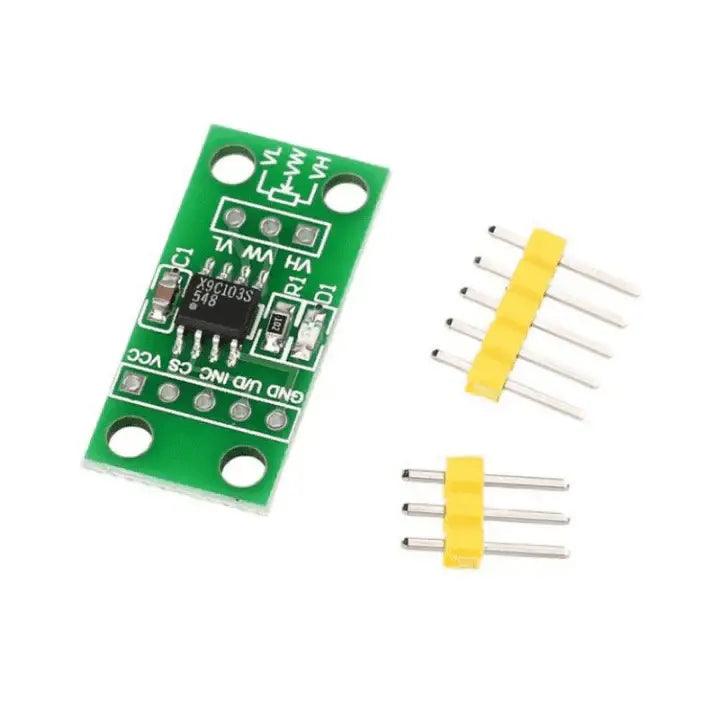
The X9C103S Digital Potentiometer Board Module is a compact, microcontroller-compatible module designed to operate within a 3V–5V DC range, making it suitable for platforms like Arduino. The X9C103 is a digitally controlled potentiometer (XDCP) that integrates a resistor array, wiper switch, control logic, and non-volatile memory.
It features a 3-wire interface for controlling the wiper position. Internally, the potentiometer consists of 99 resistive elements connected in series, forming multiple tap points. The wiper position is adjusted using control inputs such as CS (Chip Select), U/D (Up/Down), and INC (Increment). The selected position can be stored in non-volatile memory, allowing the device to retain its last setting even after power is turned off and restore it upon restart.
The module is divided into three main sections:
The resistor array includes 99 individual resistors with electronic switches at each tap point, enabling precise control. The wiper behaves similarly to a mechanical potentiometer but does not move beyond its limits, ensuring stable operation. It uses a make-before-break switching mechanism, meaning multiple connections may briefly occur during transitions, which can momentarily lower the resistance.
An internal charge pump allows operation across a wider voltage range (approximately -5V to +5V at the terminals), while maintaining a single supply. However, a small noise level (around 20 mV at 850 kHz) should be considered during circuit design.
The module is often provided with sample C language code, structured into modules such as main functions, display handling, and button control. This code can be explored using tools like KEIL for learning and testing purposes. The VL and VH pins correspond to the low and high ends of the potentiometer, supporting an input voltage range from -5V to +5V.


